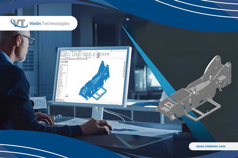
Traditional 2D drawings have served the industry for decades; however, with the growing complexity of designs and the demand for faster production, 3D CAD modeling has become increasingly essential. It not only enhances design clarity but also resolves many practical challenges faced during fabrication.
Here’s a comprehensive look at the essential 3D CAD features every sheet metal designer should use to produce error-free and efficient sheet metal models.
What we cover in this blog?
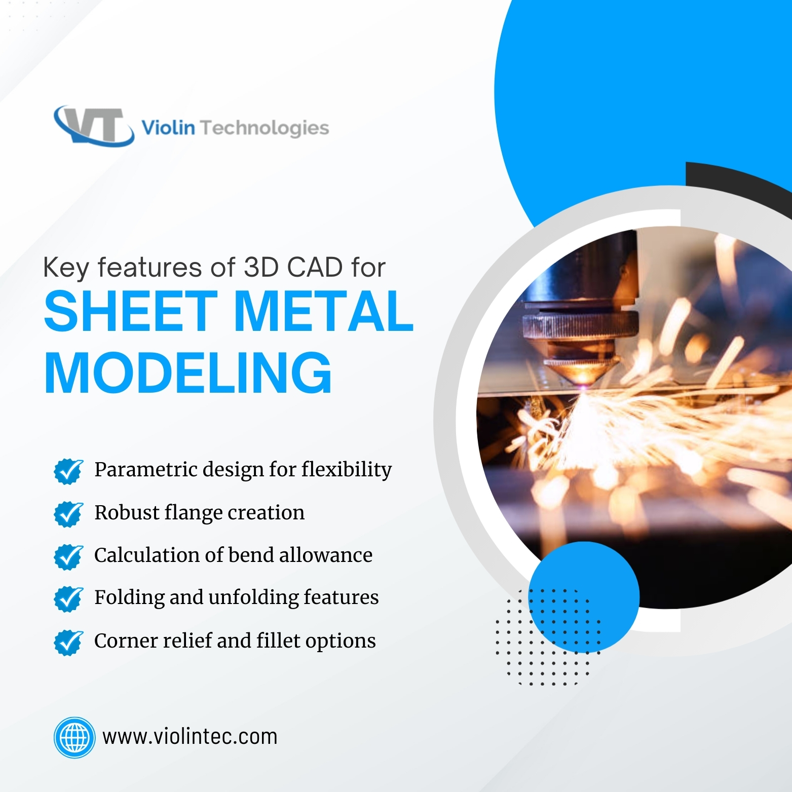
Key Features of 3D CAD for Sheet Metal Modeling
1. Parametric Design for Flexibility and Control
One of the most powerful capabilities in modern 3D CAD systems is parametric modeling. This means your sheet metal design elements are driven by parameters—dimensions and rules—that can be adjusted at any time.
Why is this important?
- Automatic updates: Change a bend radius or flange length, and the entire sheet metal model updates accordingly.
- Consistency: Ensures the relationships between bends, reliefs, and cutouts remain intact.
- Efficiency: Eliminates the need for redrawing; rapid iterations become easier and less prone to error.
In sheet metal design, where bends and folds are interdependent, parametric modeling guarantees your design stays accurate through changes, saving significant time and reducing costly errors.
Engineers can make the required changes to the design in real-time without having to start from scratch, which enables custom sheet metal manufacturers to satisfy customers’ requirements.
2. Robust Flange and Bend Tools
Bends and flanges define the shape and strength of sheet metal parts. Advanced 3D CAD software offers specialized tools that simplify the creation and adjustment of:
- Seamless generation of flanges based on selected edges.
- Ability to specify bend angles, lengths, and directions.
- Accurate control over bend radius aligned with material specifications.
- Incorporation of edge reliefs and corner treatments to prevent tearing or warping during forming.
These built-in features replace tedious manual adjustments, providing more precise and manufacturable designs.
3. Automatic Calculation of Bend Allowance and Deduction
The bending process stretches and compresses metal, altering its length. This means raw flat measurements must be adjusted for accurate fabrication.
3D CAD modeling software automatically calculates:
- Bend allowance: The extra material needed to make a bend.
- Bend deduction: The amount subtracted for accurate flat patterns.
Calculations such as material type, thickness, and bend radius, ensuring your flat patterns translate perfectly to the bent part. Automating this process eliminates the costly physical trial and error that often occurs during manufacturing.
4. Folding and Unfolding Features for Flat Pattern Generation
One of the major advantages of 3D CAD modeling for sheet metal is the ability to convert complex 3D folded parts back into 2D flat patterns used for cutting and bending.
Benefits include:
- Instant visualization of flat patterns with all bends accounted for.
- Export of DXF/ DWG files compatible with CNC cutting and punching machines.
- Ability to fold flat patterns back into 3D shapes for verification.
This feature connects design directly with manufacturing and quality control, minimizing manual errors associated with physical flattening.
5. Corner Relief and Fillet Options for Stress Reduction
Sheet metal parts with sharp corners or closely spaced bends can develop cracks or stress concentrations during the bending process. Specialized relief and fillet tools help:
- Introduce cutouts or rounded corners that reduce material stress.
- Customize sizes and types of corner reliefs based on design and manufacturing requirements.
- Prevent material distortion and cracking during the fabrication process.
By designing for manufacturability this way, parts become more robust and reliable when formed.

6. Hole, Cutout, and Tab Features
Sheet metal parts often require holes for fasteners or cutouts to accommodate other components. CAD modeling software provides:
- Precise positioning and size controls for holes and cutouts.
- Options to create various hole types—circular, slots, countersunk, etc.
- Design and placement of tabs that facilitate assembly or provide supplementary support.
These features enable detailed and functional sheet metal designs to align precisely with assembly and usage scenarios.
This is critical for sheet metal and stamp part manufacturers, who regularly work with complicated designs that require precise accuracy to match customer specifications. CAD designs are more accurate, waste less material, speed up production, and ultimately save time and money.
7. Material Library and Thickness Management
Material properties significantly influence the behavior of sheet metal. Modern CAD tools include:
- Databases of common metals like aluminum, steel, stainless steel, and more.
- Physical properties such as elasticity, yield strength, and thermal expansion.
- Integrated control of sheet thickness, enabling quick changes across the model.
This integration helps simulate real-world conditions and optimize designs based on material constraints.
8. Bend Order and Sequence Specification
The sequence in which bends are made affects part accuracy and prevents collisions or interference during the forming process. 3D CAD software allows you to:
- Specify the exact order of bends.
- Control that bends doesn’t obstruct subsequent operations.
- Automatically update bend sequences when the design changes.
Maintaining correct bend sequences reduces manufacturing difficulties and improves overall product quality.
9. Design Validation and Simulation
A 3D CAD solution tailored for sheet metal should include validation tools that:
- Simulate bending to visualize stress, deformation, and potential failure points.
- Detect collisions, overlaps, or unachievable geometries before fabrication to ensure optimal results.
- Analyze flat pattern accuracy and assembly compatibility to ensure optimal results.
Simulations significantly reduce the need for costly prototype iterations, ensuring your design meets performance and safety criteria before production.
10. CAM Integration and CNC Compatibility
Effective sheet metal design doesn’t end with modeling. Seamless integration with CAM (Computer-Aided Manufacturing) tools allows:
- Automatic generation of CNC machine instructions, including cut, bend, and punch commands.
- Transfer of precise design data to manufacturing workflows.
- Quick adaptation to changes in design or material specifications.
This end-to-end digital workflow enhances speed, accuracy, and consistency in the fabrication of sheet metal.
Conclusion
3D CAD modeling has transformed sheet metal design by providing specialized, powerful tools tailored to the unique requirements of bending thin metal sheets. From parametric flexibility and precise flange creation through automatic flat pattern unfolding, relief design, and material optimization, these features collectively enable designers to predict manufacturing outcomes, reduce waste, and improve speed to market.
Investing in CAD software equipped with these essential sheet metal capabilities leads to fewer errors, better product performance, and streamlined collaboration between design and manufacturing teams.
For engineers working with sheet metal, mastering these features is a vital step towards producing high-quality, manufacturable parts that meet today’s demanding industry standards.
FAQs
1: Why is parametric design important for sheet metal modeling?
Parametric design lets you easily update dimensions and features, ensuring all bends and parts adjust automatically without redrawing.
2: How does automatic flat pattern generation help in sheet metal design?
It creates accurate 2D unfolding of 3D models that match real bends and allowances, making fabrication faster and error-free.
3: What roles do corner relief and fillet features play in sheet metal CAD?
They prevent sharp edges and reduce stress points to avoid cracking or tearing during bending and forming.
4: How does integrated material data improve sheet metal CAD modeling?
Built-in material libraries allow accurate thickness, bend allowance, and behavior calculations, aligning design with manufacturing reality.

